About
Projects
Experiences
Links
The goal of this project is to build our own first robot, which later should be able to follow a line autonomously.
The main components of the robot are the raspberry pi and the camera onboard, which will be used to help us follow the line correctly.
We'll set the following goals for this project :
The projet was made in collaboration with the Enseirb MatMeca Engeneering School, whose students helped us by joining our group and working on the project. We had limited time to work on the project, approximately three days, starting on Tuesday, and presenting our work on Friday afternoon.
The first steps of the project was to distribut the tasks. Since the MatMeca students were more familiar with physics and kinetics, they worked on the robot's odometry and movements in space. On the other hand, me and the other University students worked on the image processing, the robot's frame and the integration of the components. So we started by drawing the frame of the robot on a CAD software named OnShape, a cloud-based software, we later moved on Fusion360 to finish the design. After assembling the robot, the final look was something like this :
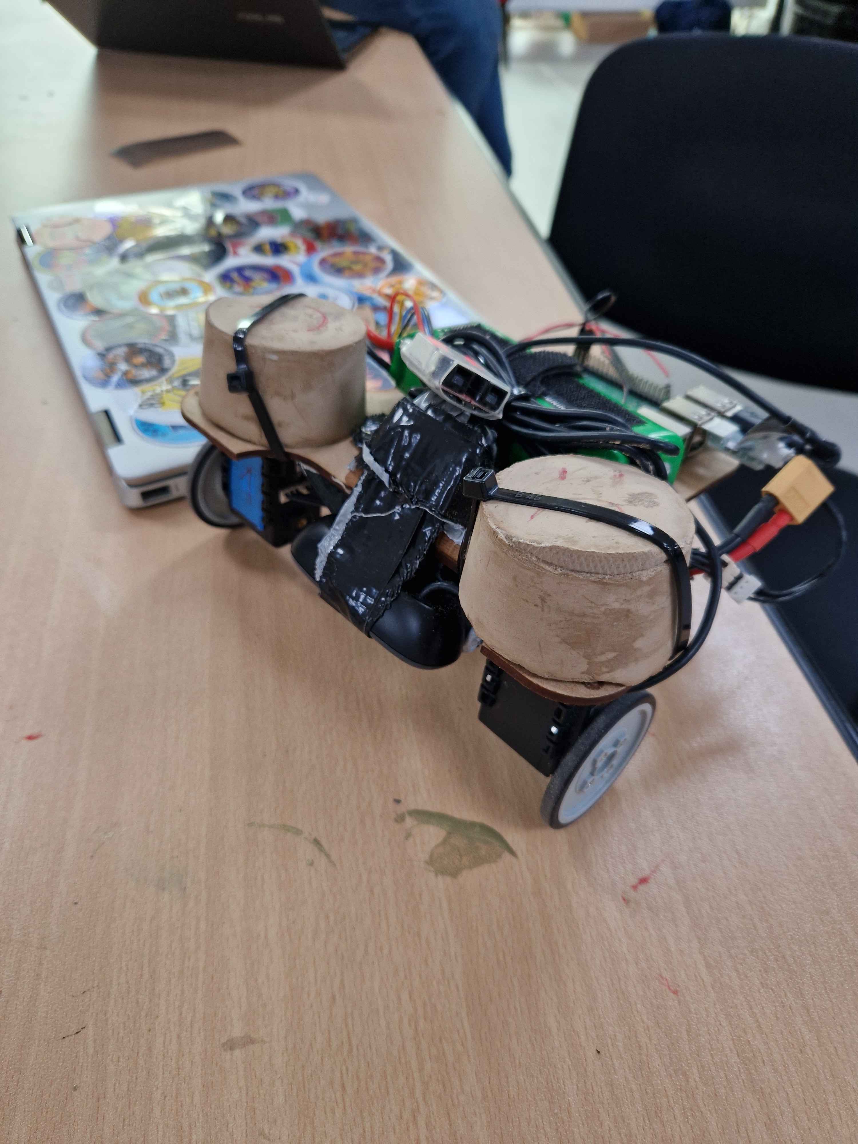
Our FirstRobot's final look
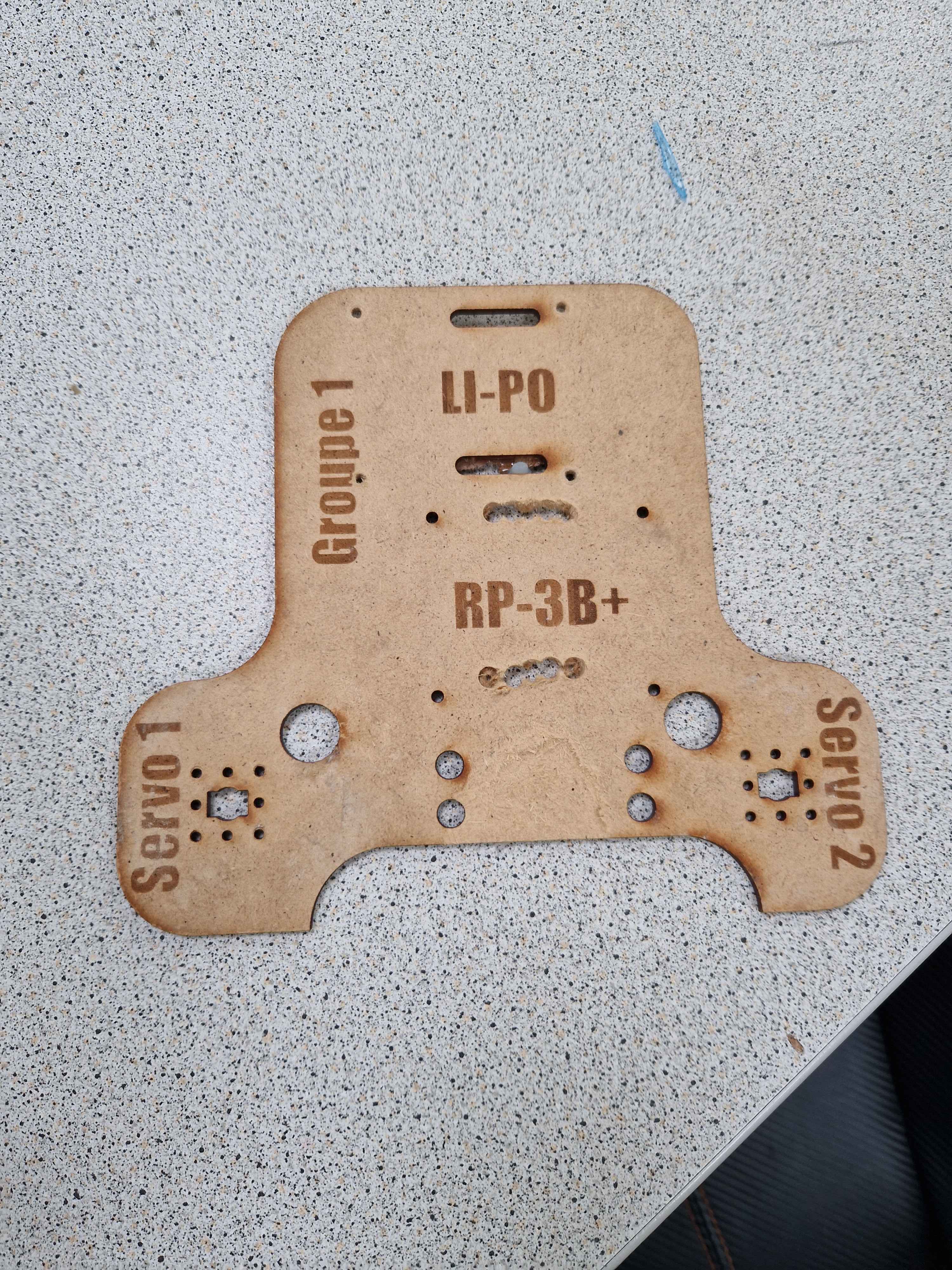
Robot frame design
The langage used for the project was Python, and the main libraries used were OpenCV and PyPot. OpenCV was used to process the images and extract the visual features, and PyPot was used to control the robot's movements. And for the raspberry pi, we used the Raspbien OS as recommanded.
At this point we needed to find a reliable algorithm to find and follow a line on the floor correctly, and we had two choices. The first one was to make a mask to filter the color we're looking for, make the image black and white to easily work on it, and use an histogram to measure the intensity of the pixels. The second approach was to use an OpenCV well known algorithm, the border detection, which would look for the longest continuous line on the image and keep it. We decided to keep the first approach, which probably caused a couple problems we'll mention later.

video demonstrating the line-following capabilities
On the video above, we have a live feed of the camera mounted on the robot as he tries to follow the line. The robot movements have been adapted with the image processing, we divided the image in six different parts, and first the robot would move on the direction of the part with the most white pixels from the histogram, the three different parts on each side would help the robot calibrate how hard and how fast he can turn, each three parts on the left and right side have weights, so if the most pixels are on the left side part in the part the closest to the middle, the robot would turn left lightly.
One major problem we encountered during this exercise was caused by one of the lines. The first one we would follow is a red line, which is a pretty straight forward color to detect and follow, but the problem was the second line which was black, on a grey floor, and a lot of lightning variations in the room. Because of these conditions, the histogram probably wasn't the most adequate choice, where the border detection would have been more reliable. We still managed to make it work !
Robot following the black line
Robot following the red line
The MatMeca students worked on the robot's odometry and kinetics, and they managed to make the robot move in space, and follow a trajectory. The robot was able to move forward, backward, turn left and right, and even make a full 360° turn. The main goals were the following :
The final results were very satisfying and the robot was able to move in space to specific coordinates, and draw a fairly accurate map of the circuit.
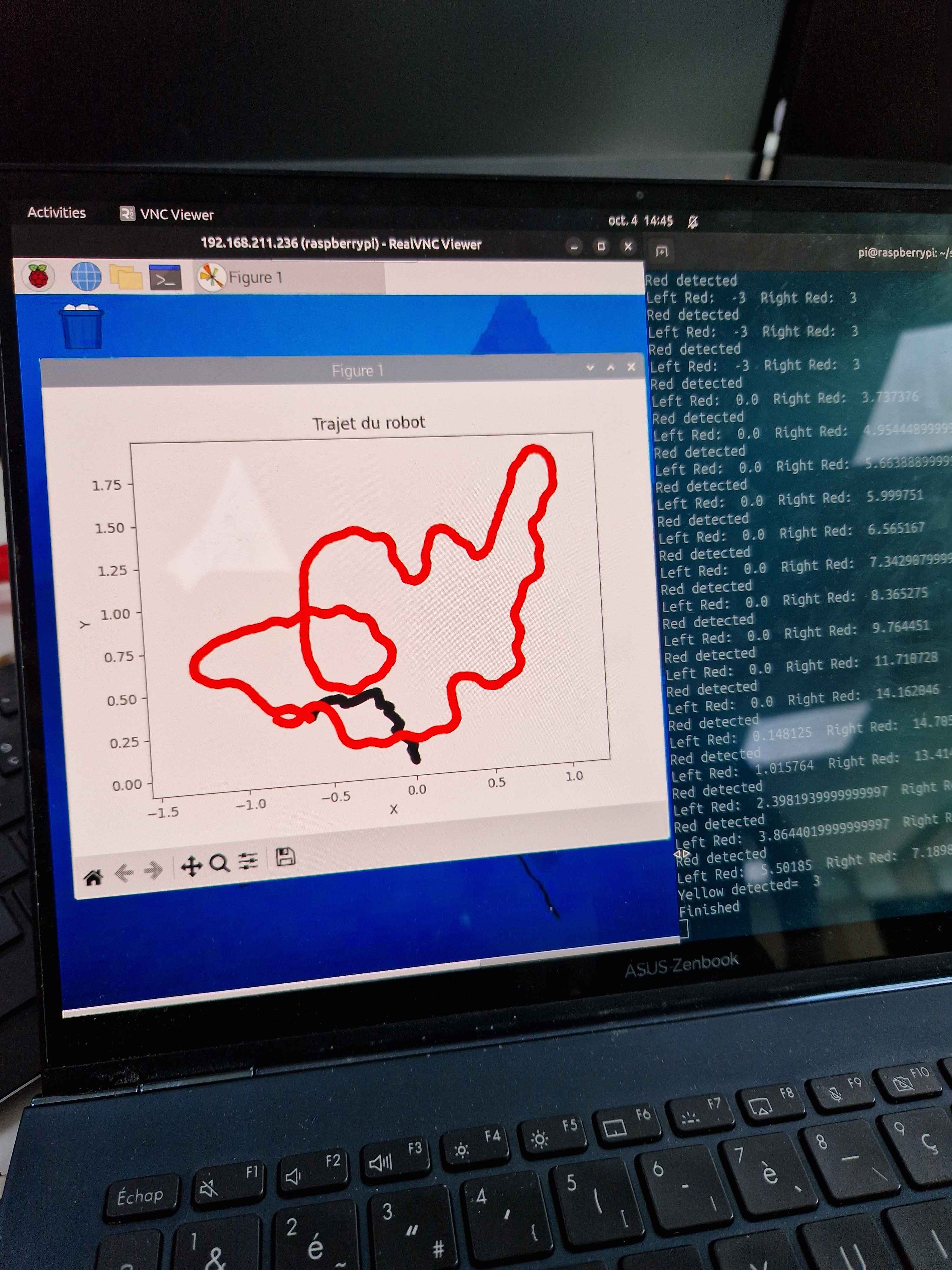
Odometry line mapping
Odometry demonstration video of the robot moving to (0,1) coordinates and facing 180°